The NAND gate is the most important logic gate in digital electronics and integrated circuits. IC7400 is a popular IC that consists of 4 NAND gates. The biggest importance of NAND gate is that it is one of the universal logic gates using which other logic gates can be implemented. Construction of basic logic gates using NAND gate, XOR gate using NAND gate and XNOR gate using NAND gate are shown in three different articles. In this article, we are going to discuss the logic circuit and truth table of NAND gate using 2 and 3 inputs.
Contents in this article:
- What is a NAND gate?
- Symbol of NAND gate
- NAND gate with two inputs
- NAND gate with three inputs
- Truth table of NAND gate with two inputs
- Truth table of NAND gate with three inputs
- Use of NAND gate
What is a NAND gate?
A NAND gate consists of an AND and a NOT gate in series. NAND gate is a classical logic gate that gives the output as the complement of the multiplication of the inputs. That means it gives the complementary output of an AND gate. This can be understood from the Boolean expression and truth table which are given below.
Boolean equation for NAND gate
A NAND gate can have an infinite number of inputs and only one output. If A, B, C, D,…. be the binary inputs of a NAND gate then the expression for the Boolean output will be \small \textbf{Y=} \overline{\textbf{ABCD…}}. For two-input NAND gate we will take up to two inputs and for three-input NAND logic we will take up to three inputs.
Logic circuit and truth table of NAND gate using 2 inputs
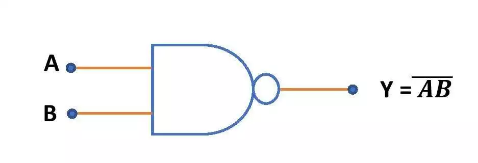
A two-input NAND gate will have two inputs and only one output. The circuit symbol and the truth table of a NAND gate with 2 inputs are shown below.
Logic circuit of 2 input NAND gate
The circuit symbol of a two input NAND gate is like this –
Truth table of NAND gate with 2 inputs
Let A and B be the two inputs in a NAND gate and the output is taken at Y. Then the truth table for a two input NAND gate is as follows. It gives low output when both the inputs are high. In all other combinations of inputs, it shows high output.
| Input (A) | Input (B) | Output \small \textbf{Y=} \overline{\textbf{AB}} |
| 0 | 0 | 1 |
| 0 | 1 | 1 |
| 1 | 0 | 1 |
| 1 | 1 | 0 |
Logic circuit and truth table of NAND gate with 3 inputs
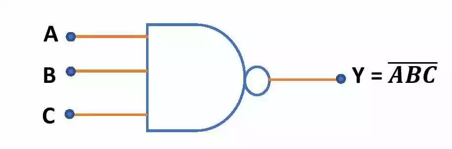
A three-input NAND gate will have three inputs and only one output. The circuit symbol and truth table of NAND gate with 3 inputs are as below.
NAND gate logic circuit using 3 inputs
Here is the circuit symbol of a NAND gate with three inputs.
Truth table of NAND gate with 3 inputs
Let A, B and C be the inputs in a NAND gate and the corresponding output is Y. Then the truth table for three input NAND gate is as follows. 3 input NAND gate gives low output when all inputs are high. Otherwise, it gives high output.
| Input (A) | Input (B) | Input (C) | Output \small \textbf{Y=} \overline{\textbf{ABC}} |
| 0 | 0 | 0 | 1 |
| 0 | 0 | 1 | 1 |
| 0 | 1 | 0 | 1 |
| 0 | 1 | 1 | 1 |
| 1 | 0 | 0 | 1 |
| 1 | 0 | 1 | 1 |
| 1 | 1 | 0 | 1 |
| 1 | 1 | 1 | 0 |
Uses of NAND gate
- There is an integrated circuit IC7400 which consists of four NAND gates. This IC is used in physics and electronics practical labs to construct basic logic gates.
- One can design Multiplexer and demultiplexer circuits using NAND gates.
- Memory units of computer are also made of NAND gates.
This is all from this article on NAND gate and its circuit diagram and truth table. If you have any doubt on this topic you can ask me in the comment section. Thank you!
Related posts:
- Basic logic gates with truth tables
- Basic logic gates using NAND gate only
- XOR gate using NAND gates
- NOR gate
- XNOR gate using NAND gate only
- Boolean algebra
- Karnaugh map (K-map)
Comments are closed.