Earlier we discussed the basic logic gates with truth table, circuit diagram and Boolean expression. The three basic logic gates in Computers are OR gate, AND gate and NOT gate. The universal logic gates like NAND gate and NOR gate are also introduced to you. All logical gates can be designed by using universal logic gates. In other two articles, we learned how to implement XOR gate and XNOR gate using NAND gates.
In this article, we are going to realize OR gate, AND gate and NOT gate i.e. basic logic gates using NAND gate only. Here you will get the circuit diagrams and Truth tables for basic logic gates using NAND gates only.
Contents of this article:
- Realize OR gate using NAND gate only
- Implement AND gate using NAND gate only
- Realize NOT gate using NAND gate only
Circuit diagram of OR gate using NAND gates only
The diagram at below is the circuit diagram of two input OR gate using NAND gate only.
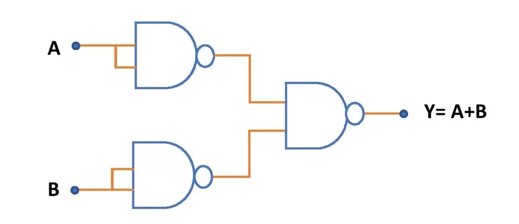
If A and B be the inputs of an OR gate then the Boolean expression is, Y = (A + B). To design a two-input OR gate using NAND gate only, three NAND gates are required.
One can verify this circuit practically. After constructing this circuit using NAND gates on a breadboard, realize the truth table. You will find the same truth table as that of an OR gate.
Circuit diagram of AND gate using NAND gates only
Here is the circuit diagram for the realization of AND gate using NAND gate only.
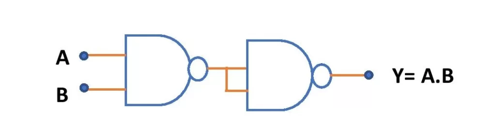
If A and B are the inputs of a two-input AND gate then the Boolean expression is, Y = A.B. To design the AND gate using only NAND gate, we need two NAND gates. One can verify the truth table of this circuit also.
Circuit diagram of NOT gate using NAND gate only
Here is the circuit diagram of NOT gate using NAND gate.
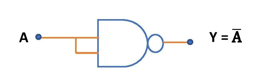
We know that a NOT gate has only one input and it gives the output as the complement of the input. To realize the NOT gate using NAND gate, we need only one NAND gate. Practical verification of this circuit is also possible, just like that of the OR gate and AND gate.
This is all from this article on the implementation of basic logic gates using NAND gates only. If you still have any doubt on this topic you can ask me in the comment section.
Thank you!
Related posts:
- XOR gate using NAND gate and NOR gate only
- XNOR gate using NAND gate and NOR gate only
- NAND gate with 3 inputs
- NOR gate circuit and Truth table
4 thoughts on “Construction of basic logic gates using NAND gate”
Comments are closed.