NOR gate is one of the universal logic gates along with the NAND gate. Do you know how to make NOR gate? How does NOR gate work? One can make a NOR gate by connecting an OR gate and a NOT gate in series. So, the main work of a NOR gate is to give the inverted output of an OR gate. Before understanding these things we need to know the basic things of s NOR logic gate. In this article, we are going to discuss the definition, circuit symbol, Boolean expression and truth table of NOR gate with two inputs and three inputs respectively.
Contents in this article:
- Definition of NOR gate
- Boolean expression of NOR gate
- Circuit symbol of NOR gate
- NOR gate with two inputs
- NOR gate with 3 inputs
- Truth table of NOR gate with three inputs
What is NOR gate?
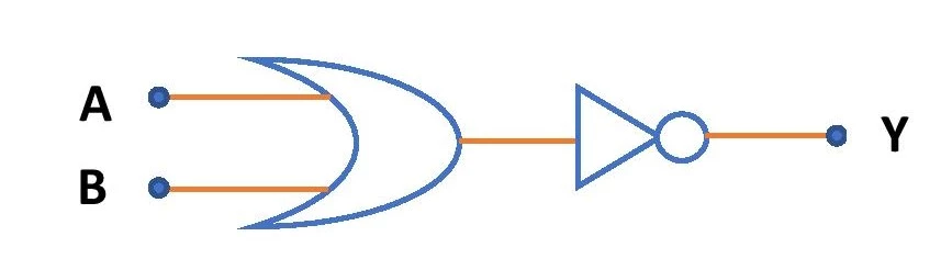
A NOR gate consists of an OR gate and a NOT gate in series. NOR gate is a logic gate that gives the output as the complement of the sum of the inputs. So, the output of a NOR gate is the complement of the output of an OR gate with the same inputs. Therefore, NOR gate is the inverter of OR gate.
Boolean expression of NOR gate
A NOR gate can have an infinite number of inputs and only one output. If A, B, C, D….. etc. be the inputs of a NOR gate then the expression for the Boolean output of the NOR logic is \small \textbf{Y=} \overline{\textbf{A+B+C+D}}.
Circuit symbol for Two Input NOR gate
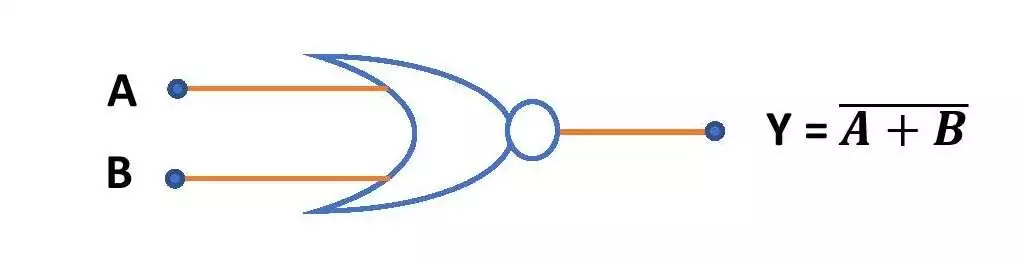
This is the circuit symbol of NOR gate with 2 inputs A and B. Here, Y is the output. NOR gate consists of an OR gate and a NOT gate. The bubble at the head of the symbol comes from the NOT gate and the rest are from the OR gate.
Truth Table for Two Input NOR gate
Here is the truth table for a NOR gate with two inputs A and B. Y represents the output of the gate.
| Input (A) | Input (B) | Output \small \textbf{Y=} \overline{\textbf{A+B}} |
| 0 | 0 | 1 |
| 0 | 1 | 0 |
| 1 | 0 | 0 |
| 1 | 1 | 0 |
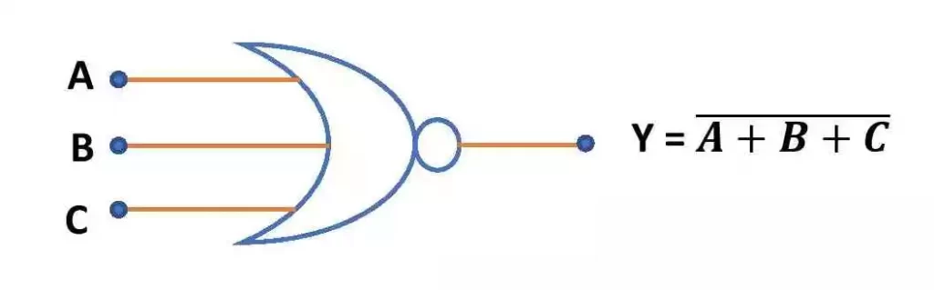
Circuit diagram NOR gate with 3 inputs
Here is the circuit symbol of three input NOR gate with the inputs A, B and C.
Truth Table of NOR gate with 3 inputs
Here is the NOR gate truth table with three inputs A, B and C. It gives the inverted output of OR gate.
| Input (A) | Input (B) | Input (C) | Output \small \textbf{Y=} \overline{\textbf{A+B+C}} |
| 0 | 0 | 0 | 1 |
| 0 | 0 | 1 | 0 |
| 0 | 1 | 0 | 0 |
| 0 | 1 | 1 | 0 |
| 1 | 0 | 0 | 0 |
| 1 | 0 | 1 | 0 |
| 1 | 1 | 0 | 0 |
| 1 | 1 | 1 | 0 |
Uses of NOR logic
- NOR gate is one of the universal logic gates. So, it can be used to develop other logic gates.
- NOR gate has decent applications in memory circuits.
- The main work of NOR gate is to provide the inverted output of an OR gate.
This is all from this article on NOR gate and its truth table and circuit diagram. If you have any doubt on this topic you can ask me in the comment section.
Thank you!
Related posts:
- Basic logic gates – OR, AND and NOT gate
- NAND gate
- XOR gate using NAND gate
- XNOR gate using NAND gate
- Boolean algebra
- Karnaugh map (K-map)

6 thoughts on “NOR gate truth table with 2 and 3 inputs”
Comments are closed.