In the previous article, we discussed Ohm’s Law of current electricity. In this article, we’re going to perform an experiment for the verification of Ohm’s law. This practical verification of Ohm’s law is very important for the students of grades 10 and 12. This is a lab-based experiment to verify Ohm’s law or Ohm’s law practical.
Aim of the Experiment
Aims of the ohm’s law experiment are as followings –
- Verification of Ohm’s Law by showing that the Voltage to Current ratio is constant.
- To determine the resistance of a wire by plotting a graph for potential difference (V) versus current (I) using Ohm’s Law.
- To find the resistivity of a wire by plotting a graph for potential difference versus current.
Theory of the Ohm’s law experiment
From Ohm’s law, we know that the relation between electric current and potential difference is V = IR
or, \color{Blue}R=\frac{V}{I} ………….. (1)
Where I is current, V is the potential difference and R is the resistance.
Again, the formula for the resistance of a wire is, \color{Blue}R=\frac{\rho L}{A}
or, resistivity, \color{Blue}\rho = \frac{RA}{L} ………. (2)
Where A is the cross-section area of the wire. A = πr2 where r is the radius of the wire. L is the length of the wire.
In this experiment, we will find the current and the potential difference across the sample wire by using Ammeter and Voltmeter respectively. Then the resistance of the wire can be found by using equation (1).
Again, We have to take at least five sets of data for different voltages and currents. Then a graph is needed to plot the current along the positive Y-axis and the potential difference along the positive X-axis.
- Ohm’s Law can be verified by finding the Voltage to current ratio. If the ratio remains constant [equation- (1)] for all sets of data, then we can say that the voltage across the resistance is proportional to the current through it which is nothing but Ohm’s Law.
- One can easily find the value of resistance of the wire from the slope of the graph. R = \frac{V}{I}
- One can find the resistivity of the wire from equation (2) by using the value of R from the graph. Usually, the examiner supplies the radius (r) or diameter (2r) and length (L). If radius and Length are not given then we have to find those by using a screw gauge and meter scale respectively.
Apparatus Used
The apparatus used for this experiment –
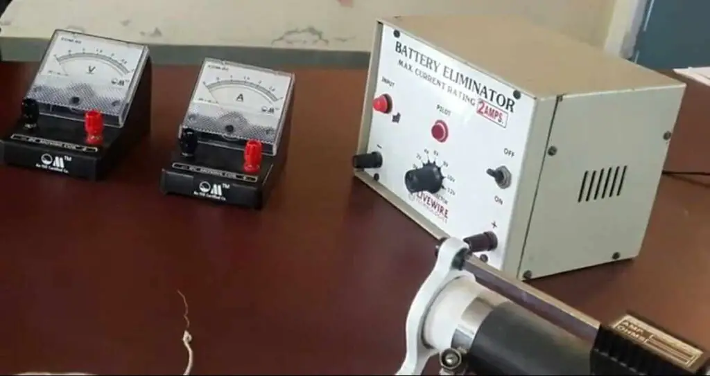
- A power supply (Voltage source or Battery): The used battery can supply the voltage from 0 to 12 volts.
- An Ammeter (A) to measure current. This Ammeter can measure the current from 0 to 3 amperes.
- A Voltmeter (V) to measure Voltage. The used Voltmeter can measure the voltage from 0 to 3 volts.
- A rheostat controls and adjusts the current through the circuit.
Circuit Diagram
Fig. (1) gives the circuit diagram for the verification of Ohm’s Law lab experiment.
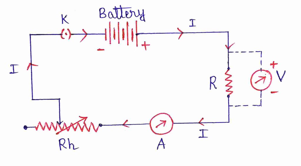
Here, R is the resistance of the wire, A is the ammeter, V is the Voltmeter, Rh is the rheostat and K is the key. The arrow sign indicates the direction of the current flow in the circuit.
Formula used for the Ohm’s law lab experiment
The formulae used for the Ohms law lab work are
\color{Blue}R = \frac{V}{I} ………….. (1)
and
\color{Blue}\rho = \frac{RA}{L} ………. (2)
Experimental data
The least count of Ammeter = Smallest division of Ammeter = 0.05 ampere
The least count of Voltmeter = Smallest division of voltmeter = 0.05 Volt
| No. of Observation | Ammeter reading (I) in A | Voltmeter reading (V) in volt | Resistance of Wire, R = V/I in ohm | Mean resistance (R) in Ohm |
| 1 | 0 | 0 | – | |
| 2 | 0.50 | 0.50 | 1.00 | |
| 3 | 0.65 | 0.65 | 1.00 | |
| 4 | 0.80 | 0.80 | 1.00 | 1.02 |
| 5 | 1.00 | 1.05 | 1.05 | |
| 6 | 1.15 | 1.20 | 1.04 |
So, we can see that in each observation the voltage-to-current ratio is almost the same. Thus, the voltage across the wire is proportional to the current through the wire. Hence Ohm’s law is verified.
Now we got the calculated value of the resistance of the wire is R = 1.02 ohm.
We also need to plot I-V graph to confirm the experimental value of R.
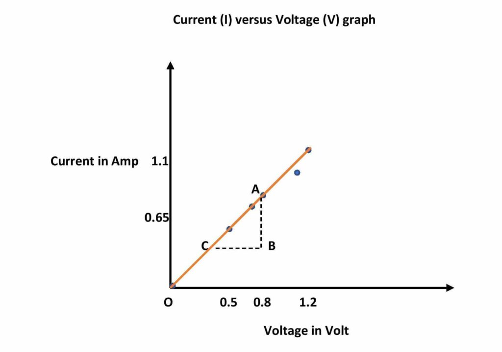
Current versus Voltage graph (Ohm’s Law graph)
If we plot the Current as a function of voltage with the help of the above data then we will get a straight line passing through the origin.
Calculations
Calculation of resistance from the graph
The inverse of the I-V graph gives the resistance of the wire.
Now, from the graph, change in current, ∆I = AB = 0.5 amp
corresponding change in voltage, ∆V = BC = 0.5 volt
Thus, the Resistance from the graph, R = ∆V/∆I = 0.5/0.5 = 1.00 ohm
Calculation of resistivity of the wire
Length of the wire is, L = 50 cm = 0.5 m
Radius of the wire. r = 0.25 mm = 0.25 × 10⁻³ m
So, the cross-section area of the wire, A = πr2 = 3.14 × (0.25×10-3)2 = 0.196 × 10⁻⁶ m2
Thus from the equation-2 we get the resistivity of the material of the wire is,
\rho = (1 × 0.196 ×10-6 )/0.5
or, \rho = 0.392 × 10-6 = 3.92 ×10⁻⁷ ohm.m
Thus the resistivity of the material of the wire is 3.92 ×10⁻⁷ ohm.m
Final result
The resistance of the wire from the Current-Voltage graph is, R = 1.00 ohm
The calculated value of the resistance of the wire is, R = 1.02 ohm.
Resistivity of the material of the wire is 3.92 ×10⁻⁷ ohm.m
Discussions
- When the voltage V = 0, the reading of the ammeter is zero. That means the current through the wire is zero. Now, one cannot calculate the resistance for this data because one cannot measure the opposition faced by the current until the current flows.
- In the last two data, the current has not increased as much as first three observations. This is because of the increase in resistance of the wire due to heating. Here current flow through the wire causes joule’s heating.
- The calculated value of resistance almost matches the resistance calculated from the graph.
- If the radius (r) and length (L) of the wire are not supplied, then we have to determine those parameters by screw gauge and the meter scale respectively.
- In this experiment 1) verification of ohm’s law is done 2) Unknown resistance of the wire and 3) Resistivity of the material of the wire is determined.
This is all from this post on experimental verification of ohm’s law. If you find this post helpful, share it with your classmates and friends.
Thank you!
Related Posts:
- Ohm’s law and all facts
- Carbon resistor Color code
- Kirchhoff’s law (KCL and KVL)
- Electrical circuit components and their uses – Resistor, Capacitor, Inductor, Diode, Transistor
- Drift velocity of electrons
- Impedance formula (L, C, LC, RLC circuits)

5 thoughts on “Verification of Ohm’s Law experiment with data and graph”
Comments are closed.