XOR gate or Exclusive OR gate is a widely used logic gate in digital electronics that is available in IC form. XOR gate can be constructed using basic logic gates, NAND gates and NOR gates separately. Again, there can be different combinations in the same group of design. We discussed basic logic gates like OR gate, AND gate and NOT gate earlier in another article. In this article, we’re going to discuss the XOR logic gate, its Boolean expression and Truth table. The circuit diagrams of XOR gate using only NAND gates or NOR gates are designed and explained as well.
Contents of this article:
- What is XOR gate?
- Boolean expression of XOR gate
- Circuit diagram of XOR gate
- Truth Table of XOR gate
- XOR gate using NAND gate
- XOR gate using NOR gate
- Application of XOR gate
What is an XOR gate?
XOR gate is also known as the Exclusive OR gate or Ex-OR gate. It gives the output 1 (High) if an odd number of inputs is high. This can be understood in the Truth Table. It can have an infinite number of inputs and only one output. In most cases, two-input or three-input XOR gates are used.
XOR gate Boolean expression
Let’s talk about a two-input XOR gate with inputs A and B. If Y is the output of the gate then the Boolean expression relating the inputs and the output is,
Y=A\overline{B}+\overline{A}Bor, Y=A\oplus B
This is the logic equation of an XOR gate. For a three-input XOR gate, the Boolean expression is Y=A\oplus B\oplus C, where A, B and C are the inputs.
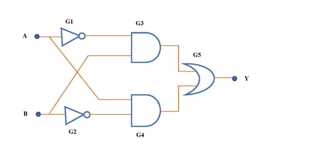
Circuit diagram of XOR logic gate using basic logic gates
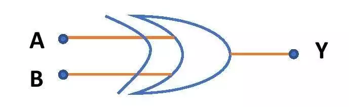
The circuit diagram for an XOR gate can be drawn in many ways by using the different combinations of NAND, NOR, NOT, AND, OR gates. It can also be designed by using NAND gates or NOR gates only. This section shows how to design XOR logic circuit using basic logic gates like AND, OR and NOT gates. Fig.1 gives the schematic circuit diagram of XOR gate and Fig.2 shows its symbol.
Truth Table of XOR gate
Table-1 and Table -2 are the Truth tables for XOR gate with two inputs and three inputs respectively.
| Input (A) | Input (B) | Output, \small Y=A\overline{B}+\overline{A}B |
| 0 | 0 | 0 |
| 0 | 1 | 1 |
| 1 | 0 | 1 |
| 1 | 1 | 0 |
| Input (A) | Input (B) | Input (C) | Output, \small Y=A\oplus B\oplus C |
| 0 | 0 | 0 | 0 |
| 0 | 0 | 1 | 1 |
| 0 | 1 | 0 | 1 |
| 0 | 1 | 1 | 0 |
| 1 | 0 | 0 | 1 |
| 1 | 0 | 1 | 0 |
| 1 | 1 | 0 | 0 |
| 1 | 1 | 1 | 1 |
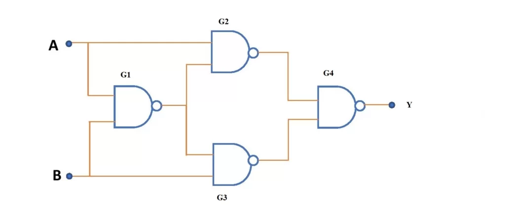
XOR gate using NAND gates only
XOR gate logic diagram can be constructed using a minimum of four NAND gates. If required, it is also possible to design an XOR gate using more than four NAND gates in a different combination. Fig.3 shows the circuit diagram for the implementation of a two-input XOR gate using four NAND gates.
Derivation of the output of NAND gate-based XOR circuit
de Morgan theorem and Boolean Algebra are used to derive the output equation of the above circuit of XOR gate using NAND gates. The used relations are \small\color{Blue}A.\bar{A} =B.\bar{B} = 0 and \small\color{Blue}\overline{AB} = \bar{A} + \bar{B}.
Let’s derive the output of the circuit!
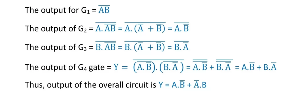
Thus the output of the above circuit is the same as the output of an XOR gate. Hence the above circuit represents the circuit diagram of Exclusive OR gate using NAND gates.
XOR gate using NOR gates only
To design the circuit diagram of an XOR gate using only NOR gates, a minimum of five NOR gates are required. XOR gate can be contained by more than five NOR gates as well. Fig.4 is the schematic circuit diagram of XOR gate using five NOR gates.
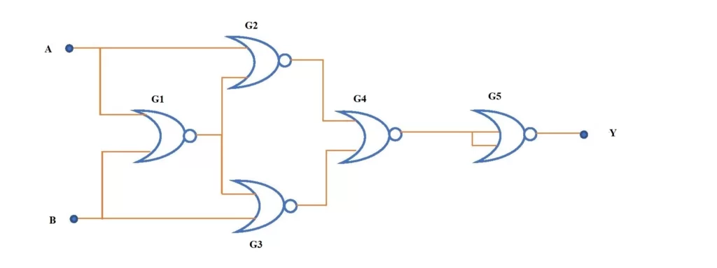
Derivation of the output of NOR gate-based XOR circuit
Here is how to obtain the output of XOR gate from the above circuit –
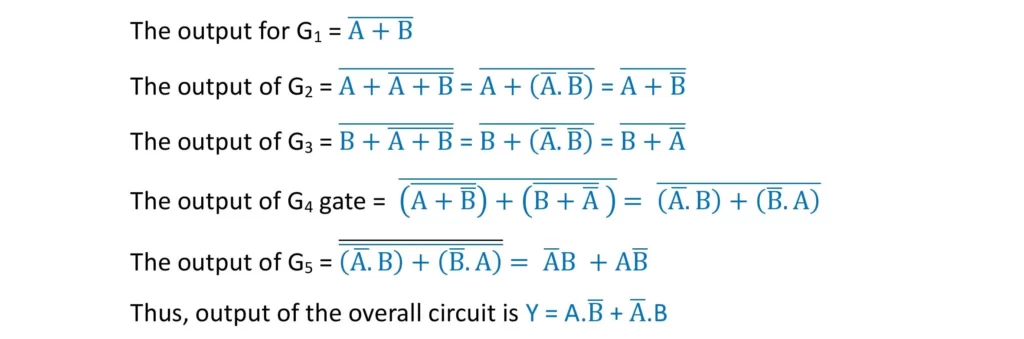
This is nothing but the output equation of the XOR gate. Hence the above NOR gate-based circuit is actually the circuit of an XOR gate. In this way, the circuit diagram of an Exclusive OR gate can be constructed by using NOR gates.
Application of XOR gate
- XOR gate has wide uses in the arithmetic section of the computer.
- The truth table of a two-input XOR gate suggests that the circuit gives the output as high (1) when inputs are unequal (when one is 0 and the other is 1). Thus, a two-input XOR gate acts as an inequality detector.
This is all from this article on the implementation of XOR gate, its diagram and truth table. Any doubts on this topic can be asked in the comment section. If you are looking for someone to help with your physics assignments, please delegate your Do my physics homework for me to experts from “MyAssignmentLab“.
Thank you!
Related Posts:
- XNOR gate using NAND gate and NOR gate only
- Basic logic gates using NAND gates only
- Basic logic gates with Truth Table and diagram – OR, AND, NOT gate
- NAND gate
- NOR gate
8 thoughts on “XOR gate circuit diagram using NAND & NOR gates only”
Comments are closed.