XNOR gate is another logical gate that is available in integrated circuit (IC) form. In other articles, we discussed that NAND gate and XOR gate are also available in IC form. Therefore, these types of logic gates are very much useful in advanced digital electronics. Basic logic gates (OR gate, AND gate and NOT gate), NAND gate, NOR gate and XOR gate are discussed in individual articles. In this article, we are going to discuss the XNOR gate circuit diagram, truth table, Boolean expression and construction of XNOR gate using NAND gates, NOR gates and basic logic gates.
Contents in this article:
- What is XNOR gate?
- Boolean expression of XNOR gate
- Circuit symbol of XNOR logic gate
- Truth table for XNOR gate
- 3 input XNOR gate
- Circuit diagram of XNOR gate with basic logic gates
- XNOR gate with NAND gate
- XNOR gate with NOR gate
- Uses of XNOR gate
What is XNOR gate?
Other names of the XNOR logic gate are Ex-NOR gate and Exclusive NOR gate. This type of logic gate can have an infinite number of inputs and only one output. XNOR gate is the inverter of XOR gate. XNOR gate gives high (1) output only if all the inputs are the same (either 0 or 1). But the output of XNOR gate is low (0) when the inputs are not equal. This can be understood in the truth table of XNOR gate. Also, one can verify this type of operation of XNOR gate practically.
Boolean expression of XNOR gate
If A and B be the two inputs of an Exclusive NOR gate then the Boolean expression for the output of XNOR gate is
\small {\color{Blue} Y = AB + \bar{A}\bar{B}}or, \small {\color{Blue} Y=A\odot B}.
This is the input-output equation for an XNOR gate.
Circuit symbol of XNOR gate
The Exclusive NOR gate is the inverter of the Exclusive OR gate. It consists of an XOR gate and a NOT gate in series which is shown below.
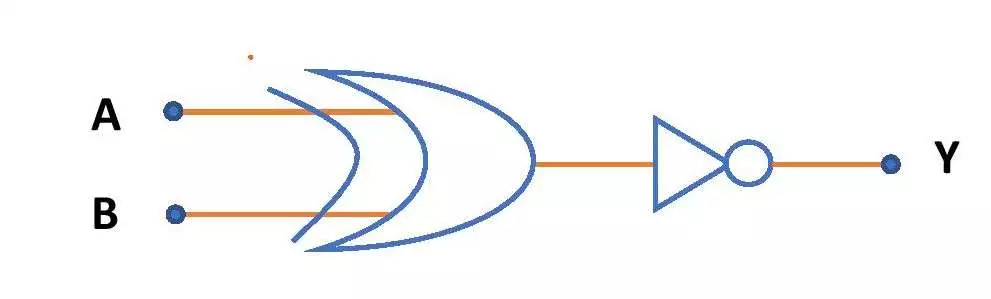
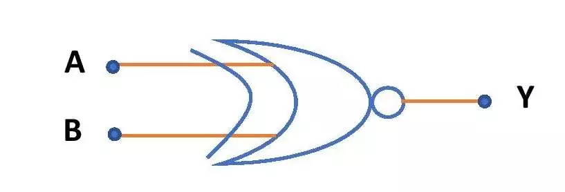
The circuit symbol for Exclusive NOR gate is shown below.
Truth table of XNOR gate with 2 inputs
Let a two input XNOR gate with the inputs A and B and the output of this gate is Y. Then the truth table for the Ex-NOR gate with two inputs is as follows-
| A | B | \small {\color{blue} Y=AB+\bar{A}\bar{B}} |
| 0 | 0 | 1 |
| 0 | 1 | 0 |
| 1 | 0 | 0 |
| 1 | 1 | 1 |
XNOR gate with 3 inputs
Let a three input XNOR gate with inputs A, B and C. Then the Boolean expression for the XNOR gate with three inputs is \small {\color{Blue} Y=A\odot B\odot C}.
The circuit symbol of the 3 input XNOR gate is the same as the circuit symbol above, but the number of inputs will be three. The truth table for this gate is shown below.
Truth table of XNOR gate with 3 inputs
Let A, B and C are the inputs and Y is the output of an Ex-NOR gate. Then the truth table of three input XNOR gate will be as followings. The outputs in the truth table of a three-input XNOR gate are just the inverted outputs of a three input XOR gate. (Check the truth table of three input XOR gate).
| A | B | C | \small {\color{Blue} Y = A\odot B\odot C} |
| 0 | 0 | 0 | 1 |
| 0 | 0 | 1 | 0 |
| 0 | 1 | 0 | 0 |
| 0 | 1 | 1 | 1 |
| 1 | 0 | 0 | 0 |
| 1 | 0 | 1 | 1 |
| 1 | 1 | 0 | 1 |
| 1 | 1 | 1 | 0 |
Circuit diagram of XNOR gate using basic logic gates
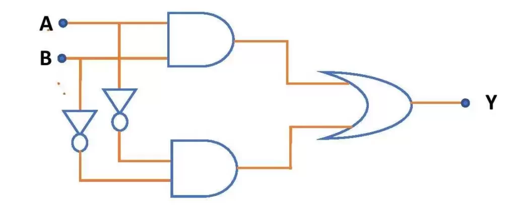
One can design the XNOR gate by using the basic logic gates like OR gate, AND gate and NOT gate. To design the XNOR gate circuit, we need two NOT gates, two AND gates and one OR gate. The above diagram is the circuit diagram for Ex-NOR gate using the basic logic gates.
Circuit diagram of XNOR gate using NAND gate
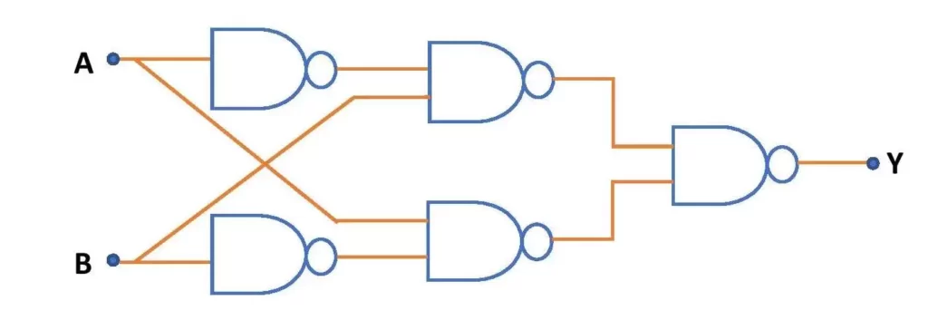
The XNOR gate circuit can also be designed by using universal logic gates like NAND gate. Minimum of five (5) NAND gates are required to design a 2-input XNOR circuit. The above picture presents the XNOR gate circuit diagram using NAND gates only.
Circuit diagram of XNOR gate using NOR gate
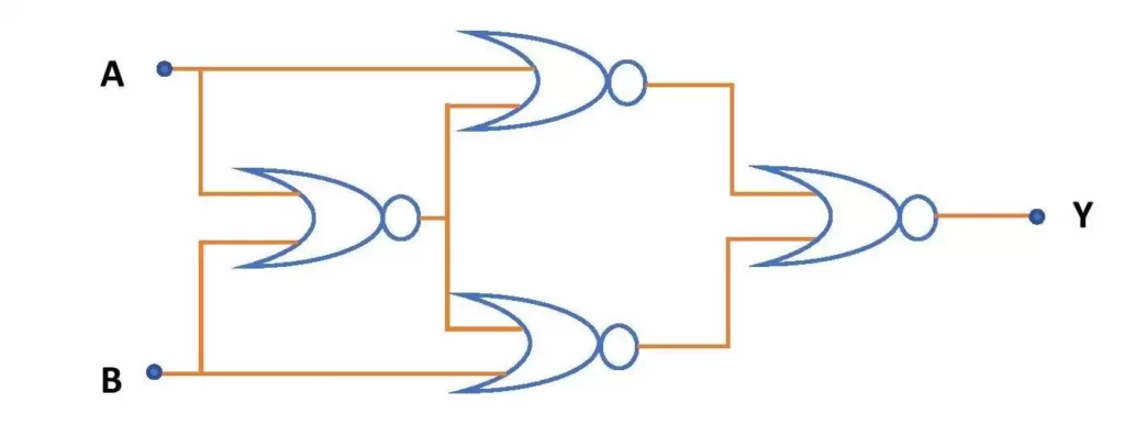
NOR gate is another universal logic gate like the NAND gate. So, one can also design XNOR circuit by using several NOR gates only. To design a two-input XNOR gate circuit by using NOR gate we need a minimum of four (4) NOR gates. The XNOR gate circuit diagram using NOR gate only is shown above.
Uses of XNOR logic gate
XNOR logic gate has some uses in digital electronics.
- XNOR gate is available in IC form. So, it has significant uses in different ICs like CMOS IC and TTL IC families.
- Exclusive NOR gate also has uses in memory circuits.
- In two input XNOR gate, we get high output when the inputs are the same. Therefore, it can be used as an equality detector.
This is all from this article on XNOR logic gate or Exclusive NOR gate and its circuit diagram using only NAND and NOR gates. If you still have any doubts about this topic, you can ask me in the comment section.
Thank you!
Related posts:
- XOR gate using NAND and NOR gates
- Basic logic gates using NAND gates only
- NAND gate
- NOR gate
- Basic logic gates
- Karnaugh map
5 thoughts on “XNOR gate circuit diagram using NAND & NOR gate”
Comments are closed.