A switch or key is useful to activate or deactivate a device. For example, if we want to ON or OFF a fan or a TV or a Tube light we need to press on switches. Sometimes, in physics laboratory, we use tapping keys to connect the circuit to get a current flow. These all keys are operated manually. In many cases, people need an automatic switch or a voltage-dependent switch. For this purpose, we’re going to discuss how an NPN transistor can be used as a switch in electronic circuits.
Contents in this article:
- Benefits of using transistor as a switch
- Transistor switching circuit
- How to use an NPN bipolar junction transistor as a switch?
- Experimental verification of transistor switching circuit
Benefits of using transistors as switches
As I mentioned that many of the circuits need an automatic or a voltage-dependent switch for safe operations. Since an electronic circuit uses currents, a voltage source is to be activated. So, if we can construct a switch whose operation depends on the current flow or the voltage applied in the circuit then it will be like a diamond. Because, in this case, we do not need to work manually, rather the current or voltage of the circuit itself decides whether the circuit will be ON or OFF.
Using a Transistor in an electronic circuit one can create such a type of switching operation in that circuit. Therefore, the application of a transistor as a switch is more useful than a manual switch. This is the advantage of transistor switching circuit.
NPN Transistor switching circuit
The circuit diagram of an NPN transistor as a switch is shown here which is a common emitter (CE) configuration circuit of an NPN transistor. It can be used as the transistor amplifier circuit as well. Just the regions of operation of the transistor are different. One can also design a similar switching circuit based on PNP Transistor as well.
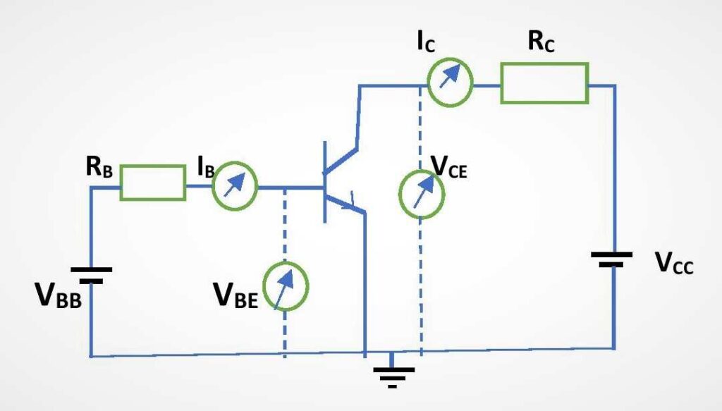
Here, VBE gives the input voltage, VCE is the output voltage, IB is the input current and IC gives the output current. We have to notice the output voltage VCE corresponding to the input voltage VBE.
Operation of a Transistor as a switch
One can realize the transistor switching operation with the help of the above circuit diagram. To operate the transistor like a switch, we need to operate in the saturation region and the cut-off region. In saturation region, it acts like a closed switch (ON stage) and in cut-off region, it acts like an opened switch (OFF stage). Now, let us realize this with some electronic equations.
Using Kirchhoff’s law in the input terminal (Base to Emitter) we get, VBB = IBRB + VBE …………(1)
And, using Kirchhoff’s law for the output terminal (Collector to Emitter) we get, VCE = VCC – ICRC …………(2)
Here, the effective input voltage is Vin=VBB which is given by equation-(1) and the effective output voltage is Vo=VCE which is given by equation-(2).
Now, for a Silicon made transistor, VBE=0.7 volt. So, when VBB is very low (less than 0.8 volts), the input current or the base current IB remains zero. At this condition, the transistor is not ON yet i.e. the transistor is at cut-off region. Then the collector current IC will also be zero. Hence, from the equation-(2) we get the output voltage, VCE = VCC (very high). Again, when VBB is very high, the base current IB will become higher. Then, the collector current IC will also become very high. This leads the transistor to saturation region of operation. Hence, the output voltage VCE becomes very low (nearly zero).
| Input voltage VBB | Output voltage VCE | Region of operation |
| Low (<0.8 V) | High (nearly VCC) | Cut off |
| High | Low (nearly 0.2 V) | Saturation |
Observation and discussion
At the ON state of a switch, the voltage across it remains very low (nearly zero) as both ends of the key are directly connected or shorted. In transistor operation, we also see that when the transistor operates in saturation region the output voltage becomes very low. This situation is like the ON state of the switch.
Again, at the OFF state of a switch, the voltage across it becomes very large as it remains open. In the cut-off region of transistors, one can achieve the same situation. So, a transistor behaves like the OFF state of a switch when it acts in cut-off region.
So, a BJT acts as ON state of a switch in saturation region and OFF state of a switch in cut-off region of operation. Clearly, the ON or OFF state of a transistor depends on the input voltage across it.
How to verify the Transistor switching operation practically?
I strongly recommend you try this circuit practically and verify the transistor switching operation for a BJT.
You need a Transistor (use BJT), a power supply (a 10-volt source is enough), a variable input voltage supply, two resistors (RB and RC), and a Multimeter to take the data for inputs and outputs.
You can place the transistor on a breadboard and construct the circuit. Note the data of output voltages for low input and high input respectively and check whether it works or not. You can measure the output voltage directly with a multimeter. However, you can calculate output voltage using equation-(2) after taking the data for the output current IC.
In this way, one can verify the working principle of a transistor as a switch.
This is all from this article. Hope you understand how to use an NPN Transistor as a switch. If you still have any doubt on this topic you can ask me in the comment section.
Thank you!
Related Posts:
- Bipolar Junction Transistor (BJT)
- Input and Output curves of a Transistor
- Difference between NPN and PNP Transistor
- Classification of BJT Amplifiers
5 thoughts on “Use of NPN Transistor as a Switch circuit”
Comments are closed.