We know that a Transistor can amplify the electric current at its output. Often, the amount of the amplified output does not meet the required criteria. That means we need the output current more than that. Then scientist Darlington proposed a new circuit arrangement with two coupled transistors which provides a huge current gain. This circuit is known as the Darlington pair amplifier. In this article, we are going to discuss the circuit diagram, theory and applications of Darlington pair amplifier.
Other names: Darlington pair, Darlington transistor, Darlington amplifier, etc.
Contents in this article:
- What is Darlington Pair Transistor Amplifier?
- Theory of Darlington pair amplifier
- Current gain and Voltage gain of Darlington pair amplifier
- Practical Darlington pair amplifier circuit
- Applications of Darlington pair amplifier
- Drawback of Darlington pair amplifier
What is a Darlington pair transistor amplifier?
Darlington Pair amplifier circuit is a connection of two transistors that acts as a single unit with an overall current gain equal to the multiplication of the individual current gains of the transistors. Darlington amplifier circuit is very popular in electronics to achieve high current gain. In this article, we are going to discuss the theory and the applications of Darlington pair amplifier.
Theory of Darlington pair Amplifier
Now, it’s time to discuss the Theory and working principle of Darlington pair transistor. The main discussions in this part are –
- Circuit diagram of Darlington pair amplifier
- Equations of Darlington pair
Darlington pair amplifier circuit diagram
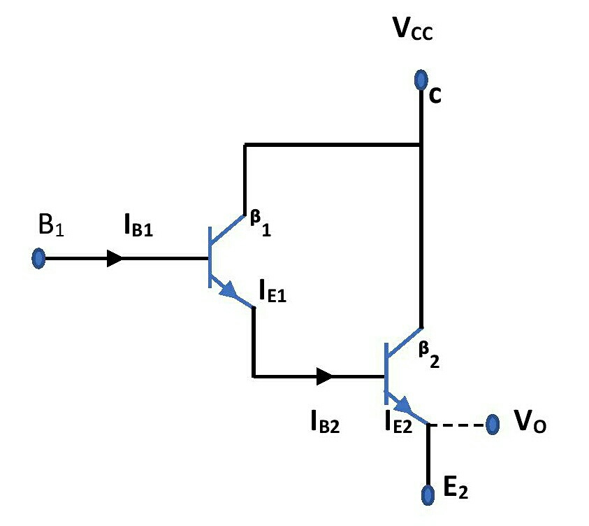
The circuit diagram for an ideal Darlington pair amplifier is shown in figure-1. Here, T1 and T2 are the two transistors. The emitter terminal of the first transistor (T1) is connected to the base of the second transistor (T2 ). So, for the overall circuit, the input current is base current of T1 and the output current is the emitter current of T2.
Equations of Darlington pair amplifier
For the transistor T1 ,
Emitter current, IE1 =( IB1 + IC1 ) = (1+_{\beta 1} ) IB1 …………… (1)
Now this emitter current will enter at the base of the second transistor T2.
So, for the transistor T2 ,
The base current, IB2 = IE1 = (1+_{\beta 1} ) IB1
Emitter current of T2 is IE2 = (1+_{\beta 2}) IB2 or, IE2 = (1+_{\beta 2} )(1+_{\beta 1} ) IB1
or, IE2 =_{\beta 1 \beta 2} IB1. Because, _{\beta 1 \beta 2} is very much higher than _{\beta 1} and _{\beta 2}. So, we can neglect the other terms in this expression.
Thus, the overall current gain is _{\beta 1 \beta 2}. This is the working principle of Darlington pair amplifier.
Typical values of _{\beta} is from 50 to 500. Most common value of _{\beta} is 99 or 100. Thus, the Darlington pair amplifier gives a very high current gain.
Current gain and Voltage gain of Darlington pair amplifier
From the above calculations, we get the current gain of the Darlington pair amplifier is almost equal to the product between the current gains of individual transistors. If _{\beta 1} and _{\beta 2} be the current gains of individual transistors then overall current gain of Darlington pair amplifier is _{\beta 1 \beta 2}.
The overall voltage gain remains slightly smaller than unity.
Practical circuit of Darlington pair
Figure-2 gives the circuit diagram of a practical Darlington pair amplifier.
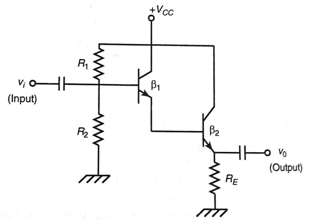
This circuit consists of two cascaded emitter followers. It also provides the same current gain as that of the ideal circuit. This two-stage emitter follower circuit has a much higher input impedance than that of a single-stage emitter follower circuit. The value of input impedance for this circuit is about _{\beta 1 \beta 2}RE. The working principle of a practical Darlington pair amplifier is also the same as that of ideal Darlington pair.
Applications of Darlington pair amplifier
We already have seen that the Darlington pair amplifier circuit can provide a huge current gain. So, it has a wide range of use as a current Amplifier. Darlington pair circuits can also be used in Voltage regulators and power amplifiers in electronic devices like TVs, computers, etc.
Drawback of Darlington pair circuit
This circuit is very useful in amplifying the current. But it has a major drawback that the leakage current of the first transistor is also amplified by the second transistor. As a result, there is a possibility of burning out the circuit due to the generation of high temperature by this huge leakage current.
This is all about the theory and applications of Darlington pair Amplifier. If you have any doubts about this you can ask me in the comment section. Also, you can visit all the blog posts on this website for absolutely free. This website contains articles that are related to physics and electronics.
Thank you!
Related posts:
- Classification of BJT based Amplifiers- Class-A, B, AB, C, AF, RF etc.
- Basic things of a BJT Transistor
- Transistor characteristics curves
- Transistor as a Switch